


-
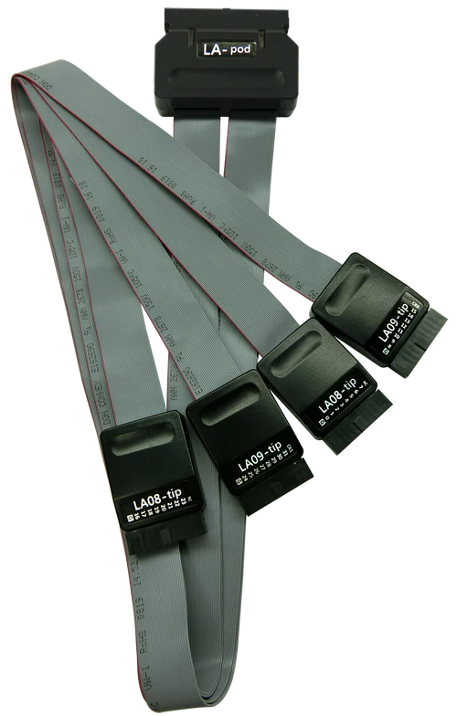
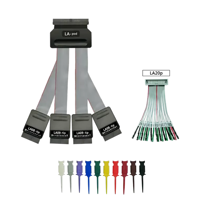
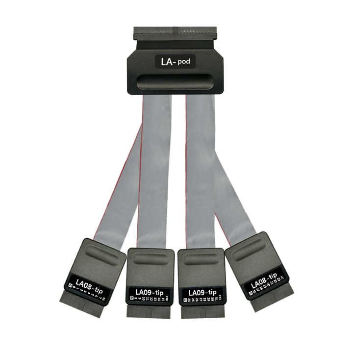
LA-Pod Solution:
Accessories Description 
1. LA08-tip: 8 Data Channel
2. LA09-tip: 8 Data Channel + 1 CLK Channel
3. Operation Voltage: -1V~8V
4. Timing Analysis: 2.4 GHz
Software:


-
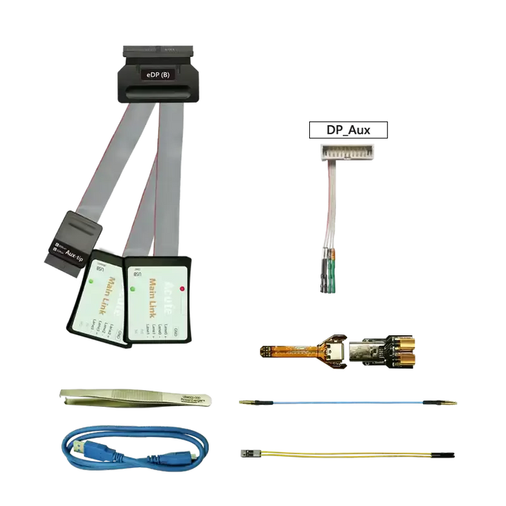
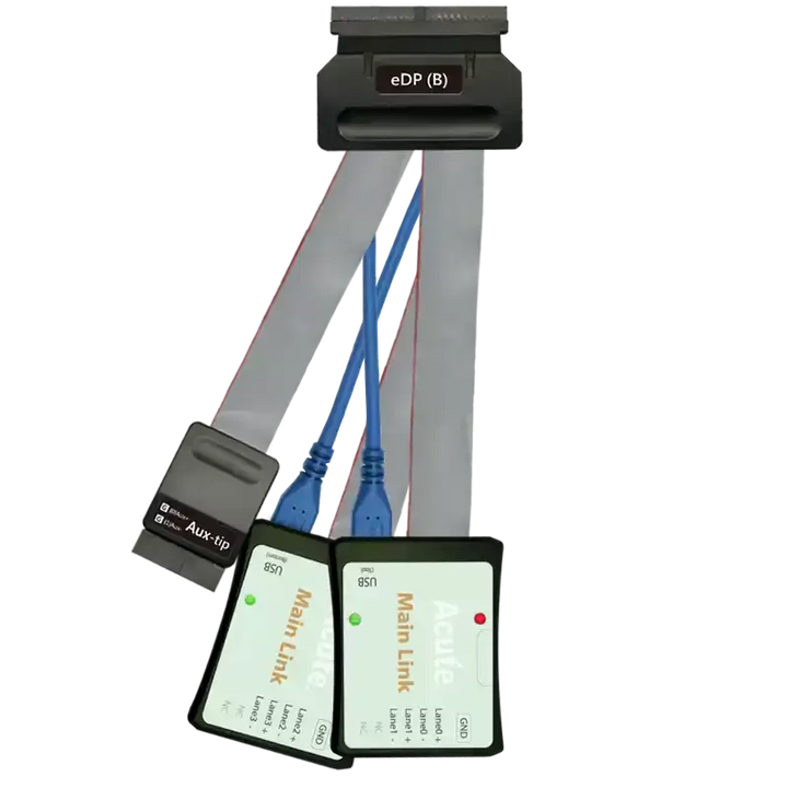
eDP1.4a:
Functions:
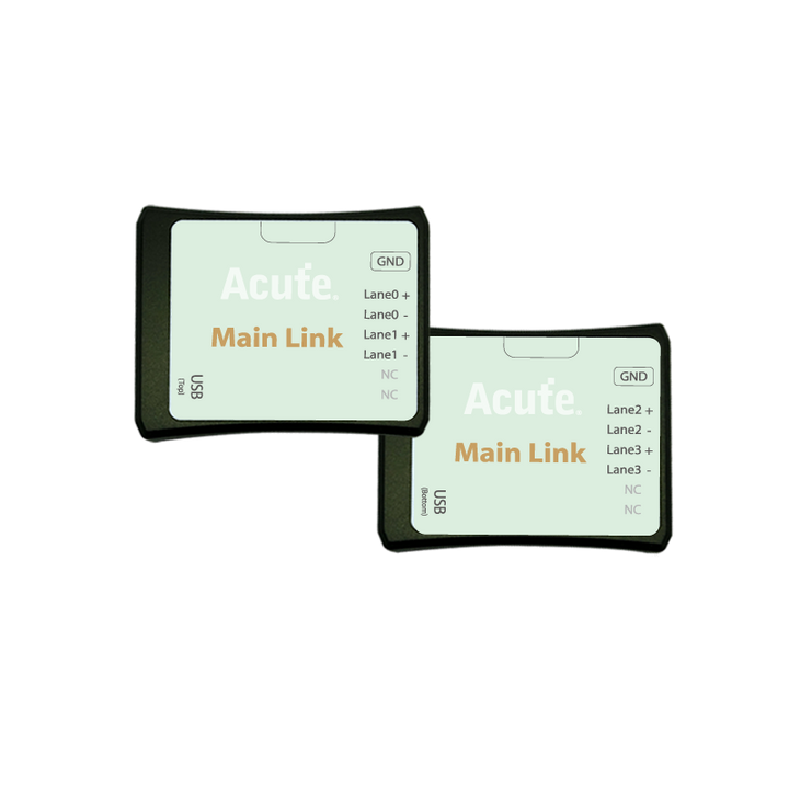
– Support eDP 1.4a,Up to 5.4Gbps,4 Lanes
– Use 32Gb RAM as the buffer to stream all eDP data into the SSD HD in order to record all data flow from Low Power Mode to High Speed Mode
– Data Filter: filters unwanted Dummy, Video data, Filling S/E to save memory
– Search: searches specific data
– Display eDP image data including RGB, YCbCr, format or compressed DSC packets.
– eDP command statistics include numbers of packets, individual command, different data length, and errors
– eDP command triggerDescription:
BusFinder device, when paired with the eDP 1.4a solution, is capable of measuring eDP V1.4a protocol analysis.Display eDP1.4a protocol packet data in table format, including DP Aux Ch command analysis

eDP Lane Skew display and statistics

Display eDP image data including RGB, YCbCr, format or compressed DSC packets. eDP command trigger, can trigger external oscilloscopes synchronously 

-
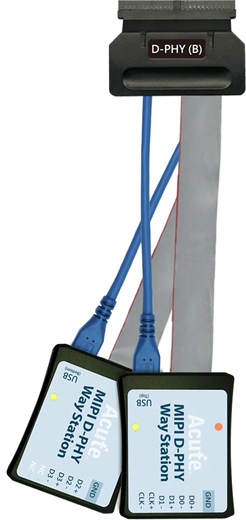
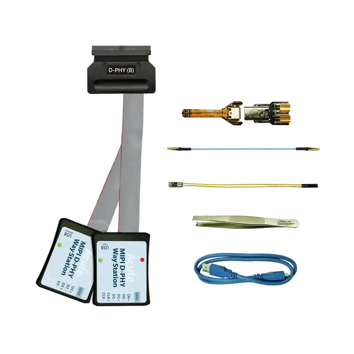
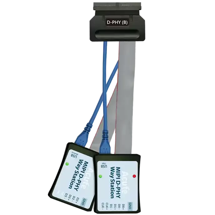
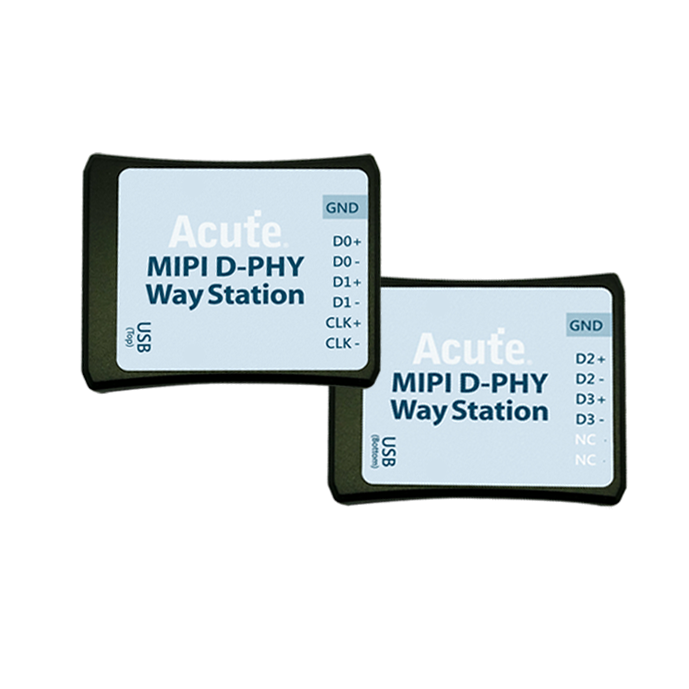
MIPI D-PHY:
D-PHY command statistics include numbers of packets
Features:
– Supports D-PHY V1.2, Up to 2.0Gbps per lane, 1 + 4 Lanes
– Display the CSI-2 1.3 or DSI 1.3 packet data in table, Includes DCS 1.3 command analysis for DSI
– Fully capture the data from Low Power Mode Initialize to High Speed Mode process
– Supports Data Filter for ignore unnecessary image data to reduce memory
– Supports Data Search function
– Supports ECC/CRC Packet Error counting and display
– Display DSI(CSI) image data including RGB, YCbCr, RAW format or compressed DSC packets, and count the Porch from raw data.
– D-PHY command statistics include numbers of packets, individual command, different data length, and errors.
– TE (Tearing Effect) Channel Detection
Description:
BusFinder with MIPI D-PHY Solution ( Way station and other components). Supports MIPI D-PHY 1.2CSI-2 1.3 or DSI 1.3 protocol packets displayed as below with the DSI DCS 1.3 commands

Display DSI(CSI) image data Porch from raw data 


-
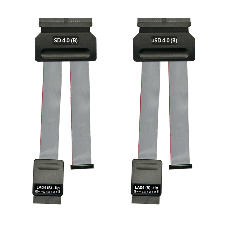
SD 4.1 (UHS II) Solution:
Features:
– Supports SD4.0 (UHS-II) Trigger、Protocol Analyzer
– Supports SD4.0 (UHS-II),Up to 1.56Gbps per laneDescription:
– The order to record all data flow from Low Power Mode to High-Speed Mode.
– “Data Filter” filters unwanted data to save memory.
– “Search” searches specific data.
– “CRC Packet” displays and counts CRC
– Can display SD4.0 protocol packet data in tabular form, including command parsing
– SD4.0 command statistics include numbers of packets, individual commands, different data lengths, and errors
– SD4.0 command trigger
– VDD DetectionCan display SD4.0 protocol packet data in tabular form, including command parsing
 SD 4.0 command statistics
-
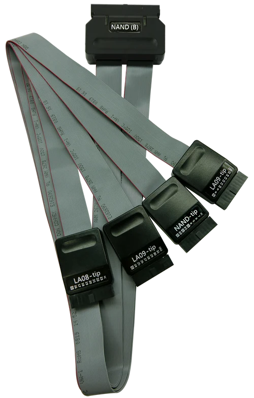
NAND Flash Solution:
Features:
– Support Data(I/O) pin: x8, x16
– Support Various Vendors: Hynix, Intel, Micron, Samsung, ST, Toshiba, Winbond, Macronix, Cypress(Spansion), ONFI, Dosilicon, ESMT, Zetta, GigaDevice, etc. (Also support Custom data)
– Support ONFI 4.1(NV-DDR3),Mode 8 / Toggle DDR 2.0 ~267MHz
– Timing Check (Logic Analyzer Mode Only. It can be enabled in bus decode settings.)Description:
Display NAND Flash protocol packet in tabular form, including command parsing
– Use 32Gb RAM as the buffer to stream all NAND Flash data into the SSD HDD to record all data flow from the Low-Speed Mode to the High-Speed Mode.
– Filtering unwanted data.
– Searching for specific data.
– Counting the times of erasing blocks.
– Statistics of NAND command includes numbers of packets and individual command.
Statistics of NAND command includes numbers of packets Individual command 

NAND trigger

Customize the NAND Command Set

-
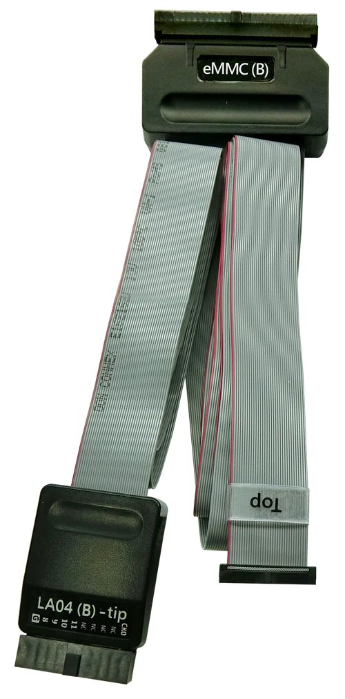
eMMC 5.1:
Features:
– Supports eMMC version up to 5.1 HS400 / HS200 / CMD Queue
– 3-Pin Mode:If you only need to analyze the waveform data of CMD and BUSY, 3-Pin Mode will be a good choice. You do not need to connect all the pins in the measurement. You only need to connect the CLK, CMD, and D0 pins to measure the CMD data.
– No Clk Mode:If you need to record the CMD waveform data for a long time, you can ONLY connect CMD pin. Then you can do the CMD analysis with transitional storage.Description:
– The order to record all data flow from Low Power Mode to High-Speed Mode.
– “Data Filter” filters unwanted data to save memory.
– “Search” searches specific data.
– “CRC Packet” displays and counts CRC
– Can display eMMC/MMC 5.1 protocol packet data in tabular form, including command parsing
– eMMC/MMC 5.1command statistics include numbers of packets, individual commands, different data lengths, and errors
– eMMC/MMC 5.1 command trigger
1. Settings 2. Data Phase Tuning 

3-Pin ModeNo Clk Mode
Can display eMMC protocol packet data in tabular form, including command parsing

-
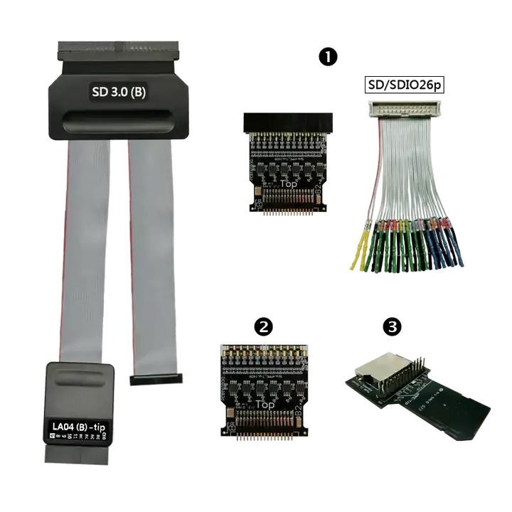
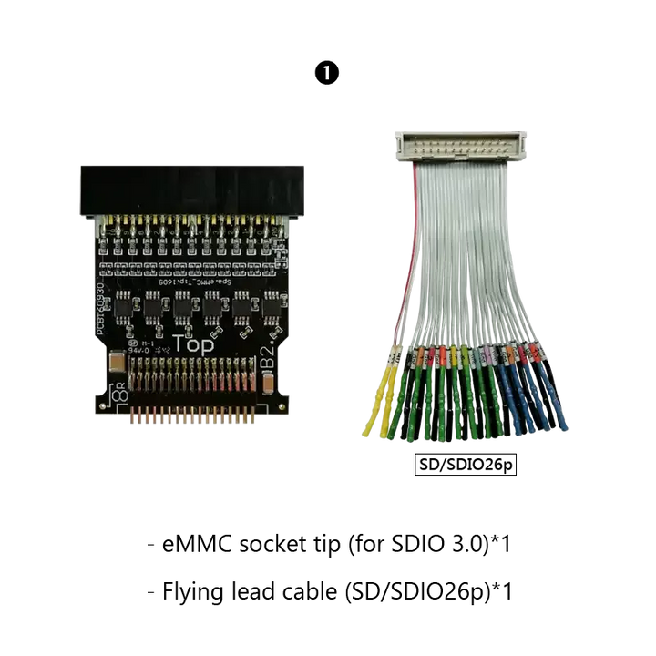
SD3.0/SDIO3.0:
Functions:
– Supports SD 3.0 SDR104 / SD6.0 Legacy mode SDR104, DDR200/ SDIO 3.0
– 3-Pin Mode:If you only need to analyze the waveform data of CMD and BUSY, 3-Pin Mode will be a good choice. You do not need to connect all the pins in the measurement. You only need to connect the CLK, CMD, and D0 pins to measure the CMD data.
– No Clk Mode:If you need to record the CMD waveform data for a long time, you can ONLY connect CMD pin. Then you can do the CMD analysis with transitional storage.Description:
– The order to record all data flow from Low Power Mode to High-Speed Mode.
– “Data Filter” filters unwanted data to save memory.
– “Search” searches specific data.
– “CRC Packet” displays and counts CRC
– Can display SD6.0 Legacy mode / SD 3.0 protocol packet data in tabular form, including command parsing
– SD6.0 Legacy mode / SD 3.0 command statistics include numbers of packets, individual command, different data length, and errors
– SD6.0 Legacy mode / SD 3.0 command trigger
– SD6.0 Legacy mode Command Queue
– Support SDR12、SDR25、SDR50、SDR104、DDR50、DDR200
*BusFinder provides 3 different kinds of adaptors which you can choose3-Pin Mode

No Clk Mode

SD 3.0 command statistics (Protocol Analyzer) Diagram

-
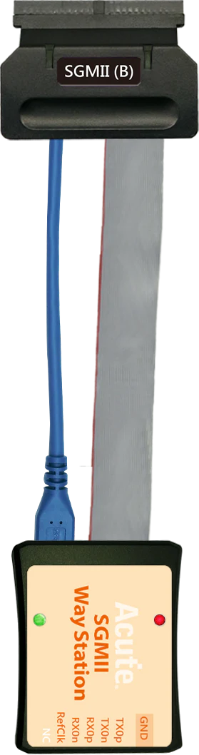
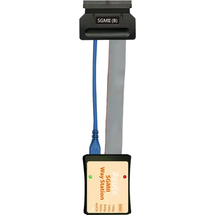
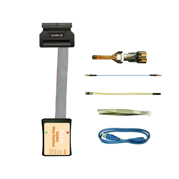
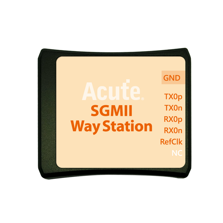
SGMII Solution:
Features:
– Simultaneously display PCS or GMII protocol packet data in tabular form, including command parsing.
– “Data Filter” & “Idle Filter” filter unwanted data and idle to save memory.
– “Search” searches specific data.
– SGMII PCS & GMII statistics include numbers of packets, individual command, different data length, and errors.
– Support 10Mbps/100Mbps/1000MbpsDescription:
SGMII command trigger
a. Trigger parameters include commands and data in order to cover all kinds of packets.
b. GMII & PCS Packet
c. Trigger CRC Error, Frame Error, Propagation Error, Start of Packet, End of Packet, Carrier Extend, Configuration.
d. The Trigger-Out port is to trigger a DSO to capture waveforms
SGMII command trigger- PCS Trigger SGMII command trigger- GMII Data Trigger 

SGMII(PHY) & GMII(MAC) packet analysis data are displayed simultaneously in the report table. The report also contains statistics on packets.

-
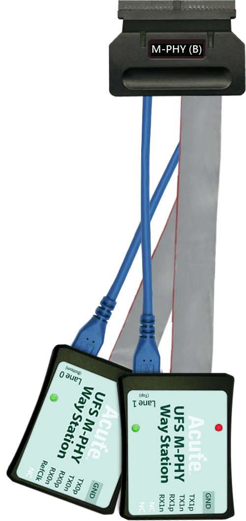
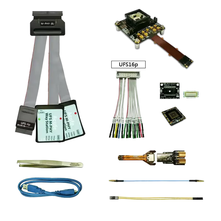
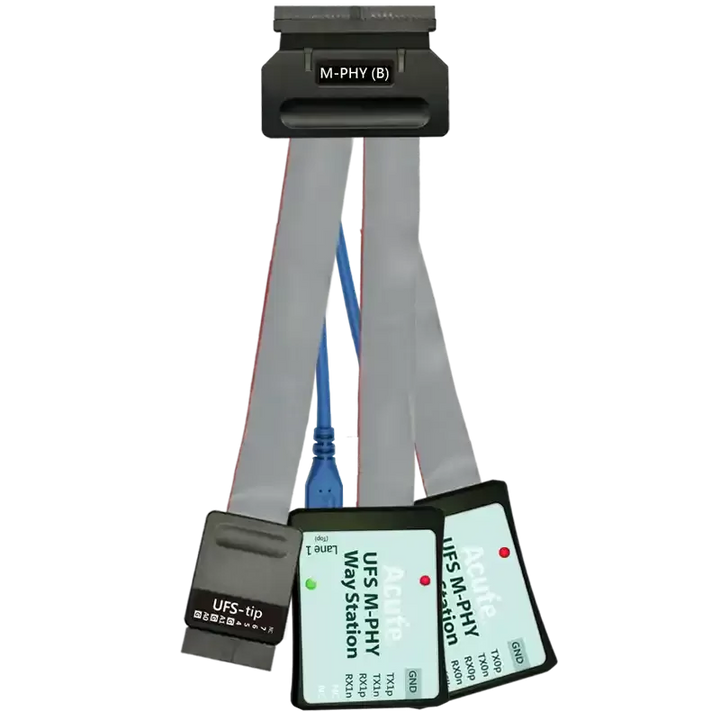
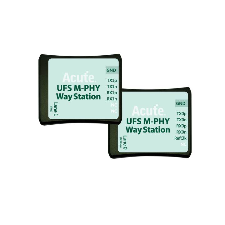
UFS2.1(BF7264B+ Only) Solution:
Features:
– Supports MIPI M-PHY 3.0, Up to 5.8Gbps ( Gear 3, Rate A / B ), 2 Lanes
– Can simultaneously display Unipro or UFS protocol packet data in tabular form, including command parsing
– Use 32Gb RAM as the buffer to stream all M-PHY data into the SSD HD in order to record all data flow from PWM Mode to High Speed Mode.
– “Data Filter” filters unwanted data to save memory.
– “Search” searches specific data.
– “CRC Packet” displays and counts CRC
– Unipro / UFS command statistics include numbers of packets, individual command, different data length, and errors
Simultaneously display Unipro Simultaneously display Unipro or UFS protocol packet data in tabular form Including command parsing 


Unipro / UFS command statistics include numbers of packets, individual command, different data length, and errors Unipro, UFS Command trigger 

Logic Analyzer (LA) Mode
-
Capture digital waveforms and support bus decodes. Able to stack with a DSO to form as an MSO.
-
Provides multiple storage modes, users could select to have long time recording or precision acquisition.

-
Long Time Record: Transitional Storage VS Compressed Storage
For signal capture and analysis, usually require to record the signal for a long time. If the data is stored in a compressed way, it will cause your software to lag or even stop functioning when decompressing the data after it is sent back to the computer. Because PC memory size might insufficient for decompressed data size. To satisfy the requirement of smooth software operation and long-term recording without missing any data, the storage method adopted by the Acute analyzer is transitional storage rather than compression. After returning to the PC software, it doesn"t need to do the decompression. The decoded results can be displayed while the analysis is finished.

Measurement
More than 20 types of waveform measurements with customized threshold settings features, provides real-time update for vertical, time and channel to channel timing measurements with statistic features.
Time:Frequency, Period, ±Duty, ±Period, Rise/Fall Time, Delay, Phase
Vertical:VMax, VMin, VHigh, VLow, Vpp, VAmp, VMid, VMean, VRMS, ±Overshoot, Rise/Fall Preshoot
Counter:Edge Count, ±Pulse Count
Math:Add, Subtract, Multiple, Divide, XY, Absolute, Square Root, LogA, LnA, Exponential, Integral

Digital Voltmeter, DVM
Provides voltage root-mean-square, voltage average and frequency
counter function for the selected channel.
 |
 |
| Measure 1 KHz, 2.5 Vpp square waveforms by the measurement function. | Measure 1 KHz, 2.5 Vpp square waveforms by the DVM function. |
| Multiple Windows | Spectrum analysis (Fast Fourier transform, FFT) |
| Multiple Window feature provides 4 display types (1x1, 2x1, 1x2, 2x2), which could displays 16 channels in maximum 4 different windows, provides clear waveform readability without lower the vertical resolution. | Apply FFT to the selected channel. |
 |

|
| Protocol Analyzer | Protocol Logger | Protocol Monitor |
| Show real-time protocol data. | Like data logger, save massive data into SSD hard drive. | Like dash cameras, record protocol data by the device’s memory only. |
| Application timing: massive protocol data with some idles in between. | Application timing: massive protocol data. | Application timing: trigger event only happens in very long time. |

|
 |

|
Protocol Analyzer (PA) Mode
It is hardware decoding, may log protocol data very long time if without waveforms. Application timing: Preliminary protocol debug.
| Digital & Analog Signals From MSO and External DSO From Other Vendors | |
| MSO Enables Digital & Analog Channels (Using the same channels) | *[1]: Decode & Digital Signals;*[2]: MSO Analog Signals;*[3]: External DSO Signals |
 |
 |
|
Stack With Other Vendors of Oscilloscope

|
 |
 |
|
Flow chart bus triggers
|
Power trigger for serial bus, 8-states flow chart setting with Counter/Timer |  |
Detail parameters for each states |

|
Analog waveform Input Sensitivity: 2mV/div to 10V/div; Max. Sampling Rate: 1GS/s @ 1Ch Can be used with High Voltage probe, Differential probe or Current probe.  |
Digital waveform
Operation Range: ±30V Max. Timing Analysis: 2GS/s @ 8Ch 
|
Additional Information
Included Items:
- Cables / Probes specific to the selected protocol -- see description above for details.
Note: Requires a BusFinder to form a complete solution.
System Requirements:
- USB 3.0 port
- 8GB PC RAM (min), 16GB (recommended)
Supported Operating Systems:
- Windows 7/8/10/11 (64-bit)