


⚠️ Note: The BF7264B+ has sold out and is officially discontinued. Understanding the importance of this tool in your work, we're dedicated to facilitating a seamless transition.
📢 We're thrilled to introduce the BF7264 Pro as its replacement, available on our website for your convenience.
Option |
BF7264B |
BF7264B+ |
|
eMMC 5.1 |
Yes | Yes |
|
MIPI D-PHY 1.2 |
Yes |
Yes |
|
NAND Flash |
Yes |
Yes |
|
SD 3.0 (SDIO 3.0) |
Yes | Yes |
| SD 4.1 | Yes | Yes |
| SGMII | Yes | Yes |
| UFS 2.1 | NO | Yes |
| Logic Analyzer Probe | Yes | Yes |
Protocol Analyzer: eMMC 5.1, MIPI D-PHY 1.2, NAND Flash, SD 3.0 (SDIO 3.0), SD 4.1 (UHS-II), SGMII, and UFS2.1
- Real-time data display, post-capture waveforms
- Trigger for commands or data
- Different active probes for different protocols for easier connections
- Filter data to save more commands
- Hide data for easy reading
- Search data for quick finding
- Statistics for commands and data
- Two voltage detects to find design bugs from voltage drop
- Use PC hard disk (SSD) to log long time data
- Protocol monitor like dash camera for long time surveillance (months)
Logic Analyzer: eMMC 5.1, NAND Flash, SD 3.0 (SDIO 3.0), Serial Flash, SPI
- 2.4GHz timing analysis
- 8-state flow chart bus triggers
- Bus decodes with waveforms
- Stacks with a DSO to form as an MSO
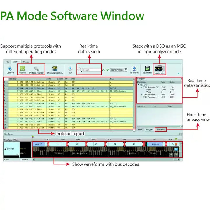
Logic Analyzer (LA) Mode
-
Capture digital waveforms and support bus decodes. Able to stack with a DSO to form as an MSO.
-
Provides multiple storage modes, users could select to have long time recording or precision acquisition.

-
Long Time Record: Transitional Storage VS Compressed Storage
For signal capture and analysis, usually require to record the signal for a long time. If the data is stored in a compressed way, it will cause your software to lag or even stop functioning when decompressing the data after it is sent back to the computer. Because PC memory size might insufficient for decompressed data size. To satisfy the requirement of smooth software operation and long-term recording without missing any data, the storage method adopted by the Acute analyzer is transitional storage rather than compression. After returning to the PC software, it doesn"t need to do the decompression. The decoded results can be displayed while the analysis is finished.

| LA Option | LVDS Option |
 |
 |
Protocol Analyzer is PC-based with USB 3.0 interface that makes it professional, reliable and cost-effective. Moreover, it acts as a Protocol logger as well as a Protocol Monitor. A very versatile tool.
Functions:
• Real-time data display, post-capture waveforms
• Trigger for commands or data
• Different active probes for different protocols for easier connections
• Filter data to save more commands
• Hide data for easy reading
• Search data for quick finding
• Statistics for commands and data
• Two voltage detects to find design bugs from voltage drop
• Use PC hard disk (SSD) to log long time data
• Protocol monitor like dash camera for long time surveillance (months)
Protocol Option:
• eDP1.5 Option:Support eDP1.5,Up to 5.4Gbps/per lane, 4 Lanes
• eMMC Option:Support eMMC 5.1 HS400 / HS200 / CMD Queue
• MIPI D-PHY 1.2 Option:Support D-PHY V1.2,Up to 2.0Gbps per lane,1 + 4 Lanes
• NAND Flash Option:Support ONFI 4.1 (NV-DDR3),Mode 8 / Toggle DDR 2.0~267MHz
• SD 3.0 (SDIO 3.0) Option:Support SD 3.0 SDR104 / SD6.0 Legacy mode SDR104, DDR200, Command Queue/ SDIO 3.0
• SD 4.1 (UHS-II) Option:Support UHS156,Up to 1.56Gbps per lane
• SGMII Option:Speed support 1000M, 100M, 10M
Support Logic Analyzer:
• 2.4GHz timing analysis
• 8-state flow chart bus triggers
• Bus decodes with waveforms
• Stacks with a DSO to form as an MSO
Option:
• LA:Support eMMC 5.1, NAND Flash, SD 3.0 (SDIO 3.0), Serial Flash (SPI NAND), SPI
• LVDS:Low-voltage differential signal measurement supporting logic signals
Protocol Analyzer
It is hardware decoding, may log protocol data very long time if without waveforms. Application timing: Preliminary protocol debug.
| Protocol Analyzer | Protocol Logger | Protocol Monitor |
|
Show real-time protocol data. Application timing: massive protocol data with some idles in between. |
Like data logger, save massive data into SSD hard drive. Application timing: massive protocol data. |
Like dash cameras, record protocol data by the device’s memory only. Application timing: trigger event only happens in very long time. |

|
 |

|
| MIPI M-PHY UFS2.1 Option | eDP1.5 Option | eMMC Option | MIPI D-PHY 1.2 Option |
 |
 |
 |
 |
| NAND Flash Option | SD 3.0 (SDIO 3.0) Option | SD 4.1 (UHS-II) Option | SGMII Option |
 |
 |
 |
 |
Additional Information
System Requirements:
- USB 3.0 port
- 8GB PC RAM (min), 16GB (recommended)
Supported Operating Systems:
- Windows 7/8/10/11 (64-bit)