CAN FD Protocol Support
AutomotiveController Area Network Flexible Data-Rate
What is CAN FD?
CAN FD (Controller Area Network with Flexible Data-Rate) is an extension of the classic CAN protocol, developed by Bosch to address the growing bandwidth demands of modern automotive and industrial networks. CAN FD maintains backward compatibility with CAN 2.0 while introducing two key improvements: larger data payloads (up to 64 bytes per frame, compared to 8 bytes in classic CAN) and faster data-phase bit rates (up to 8 Mbps or higher, while the arbitration phase remains at up to 1 Mbps). The protocol uses a single differential pair (CAN_H and CAN_L) and retains CAN's robust error detection mechanisms including CRC, bit stuffing, and automatic retransmission. CAN FD is widely adopted in automotive ECU networks, where the larger payload size reduces bus load by consolidating data that previously required multiple classic CAN frames. It is also used in industrial automation, medical devices, and aerospace applications. Protocol analysis for CAN FD is essential because the dual bit-rate operation introduces timing complexity — engineers must verify that both the arbitration and data phase bit rates are configured correctly, that bit rate switching occurs cleanly, and that all nodes on the bus can handle the faster data rate. Debugging CAN FD requires decoding frame IDs, DLC values, data payloads, CRC fields, and error frames to identify communication failures and bus-off conditions.
CAN FD Quick Reference
| type | Serial, asynchronous |
| signals | CAN_H, CAN_L (differential) |
| max Speed | 8 Mbps (data phase) |
| voltage Range | Differential |
| standard | ISO 11898-1 |
Acute Instruments Supporting CAN FD
Recommended Solutions
Recommended for Decode

TB3016B
With Analog Channels

TS3124H
with 100MHz Differential Probe
All Supporting Products

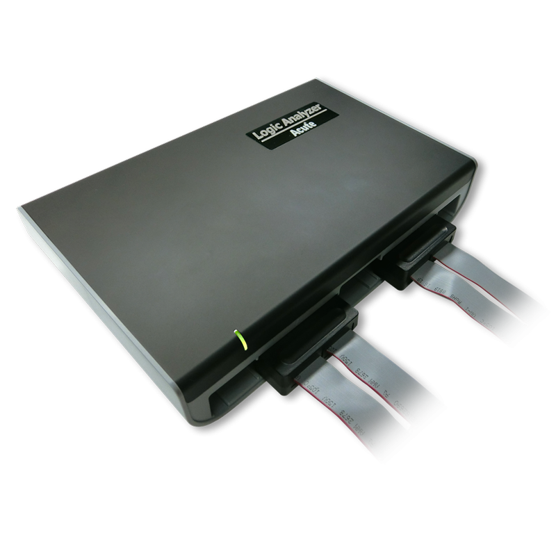


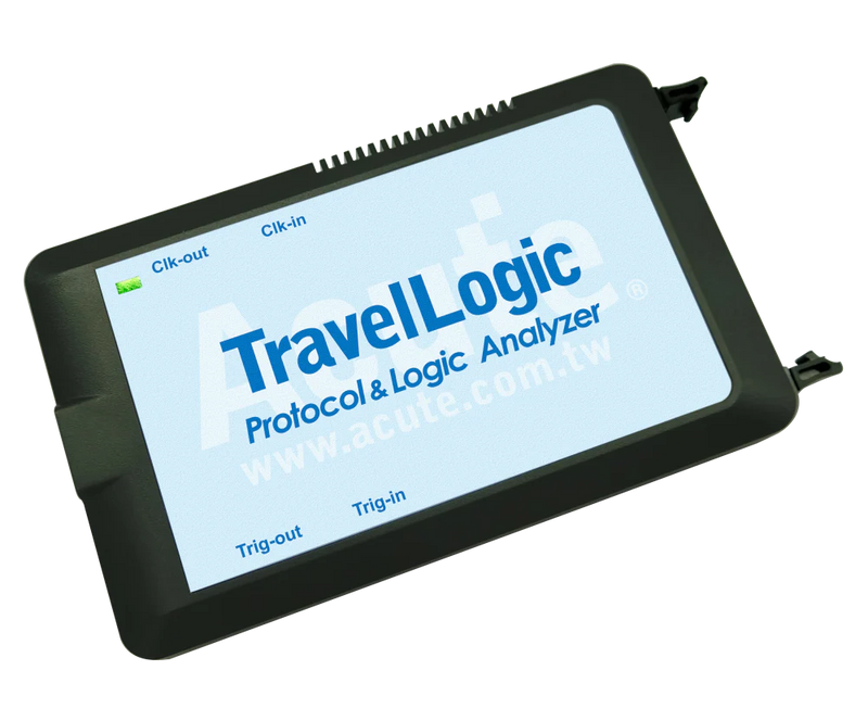
TravelBus Series


Ready to analyze this protocol?
See how Acute instruments capture and decode this protocol in real time. Request a demo or contact our team.
How to Analyze CAN FD with Acute Instruments
Connect your Acute logic analyzer to the CAN_H and CAN_L differential bus lines using appropriate probes, or tap a single-ended CAN_RX signal from the transceiver.
Attach a ground reference to the target board.
In the Acute software, select the CAN FD protocol decoder and assign the input channel(s) accordingly.
Configure the arbitration-phase bit rate (typically 500 kbps or 1 Mbps) and the data-phase bit rate (typically 2, 4, or 8 Mbps).
Capture and view decoded CAN FD frames including message IDs, DLC, data bytes, BRS/ESI flags, CRC, and any error frames detected on the bus.
Related Articles
How to Choose the Right Logic Analyzer for Your Project
A practical decision guide for selecting the right Acute logic analyzer or MSO by channel count, sample rate, protocol decode, and portability requirements.
CAN FD Protocol Analysis for Automotive Electronics
How to capture, decode, and analyze CAN FD bus traffic using Acute protocol analyzers and logic analyzers for automotive electronics development.
MSO3000: The Most Capable PC-Based Mixed-Signal Instrument
Discover how the MSO3000 combines a 4-channel oscilloscope, 16-channel logic analyzer, and 120+ protocol decoders in one USB 3.0 instrument.
CAN FD Downloads & Resources
Software
Application software for the TravelBus protocol and logic analyzer series. Windows 10/11.
Linux application for the TravelBus series. Separate native Linux app (not a Windows port) — currently in beta. Download the latest release from GitHub.