USB PD Protocol Support
PowerUSB Power Delivery
What is USB PD?
USB Power Delivery (USB PD) is a protocol specification that enables flexible power negotiation over USB Type-C connections, supporting power levels up to 240W (48V at 5A) under the Extended Power Range specification. USB PD communication occurs over the CC (Configuration Channel) line of the USB Type-C connector using BMC (Biphase Mark Coding) signaling at 300 kbps. During a PD negotiation, the source advertises its power capabilities through Source_Capabilities messages containing Power Data Objects (PDOs), and the sink requests a specific voltage and current combination through Request messages. The protocol also handles role swaps, alternate mode entry (such as DisplayPort over USB-C), battery status, and firmware updates. USB PD is now essential in laptops, smartphones, monitors, docking stations, automotive chargers, and industrial equipment. Protocol analysis is critical for USB PD development because the negotiation sequence involves precise timing requirements, and failures can result in devices not charging, delivering incorrect voltages, or failing to enter alternate modes. Engineers must verify that PDO advertisements are correct, that power contracts are established within specification timing, and that error recovery mechanisms (hard reset, soft reset) function properly. Analyzing USB PD traffic requires decoding the BMC-encoded CC line signals into readable PD messages.
USB PD Quick Reference
| type | Serial, asynchronous (CC line) |
| signals | CC1, CC2 |
| max Speed | BMC at 300 kbps |
| voltage Range | 5V – 20V |
| standard | USB PD 3.1 |
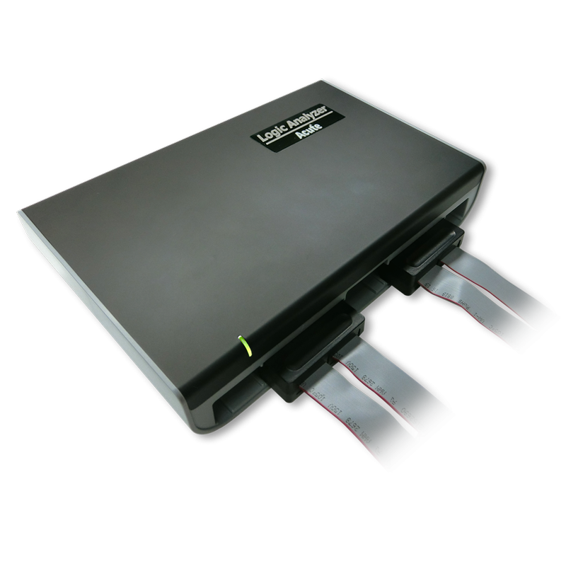
Acute Instruments Supporting USB PD
Recommended Solutions


All Supporting Products


TravelBus Series


Ready to analyze this protocol?
See how Acute instruments capture and decode this protocol in real time. Request a demo or contact our team.
How to Analyze USB PD with Acute Instruments
Connect your Acute logic analyzer or protocol analyzer to the CC1 and CC2 lines of the USB Type-C connection.
Attach a ground reference to the cable or board ground.
In the Acute software, select the USB PD protocol decoder and assign the CC line channels.
Configure the decoder for the expected PD revision (PD 2.0 or PD 3.0/3.1).
Trigger a capture during a connection event and view decoded PD messages including Source_Capabilities, Request, Accept, PS_RDY, and any error recovery sequences.
USB PD Downloads & Resources
Software
Application software for the TravelBus protocol and logic analyzer series. Windows 10/11.
Linux application for the TravelBus series. Separate native Linux app (not a Windows port) — currently in beta. Download the latest release from GitHub.