I2C Protocol Support
Embedded SystemsInter-Integrated Circuit
What is I2C?
I2C (Inter-Integrated Circuit) is a synchronous, multi-master, multi-slave serial communication bus invented by Philips Semiconductor. It uses just two signal lines — SDA (Serial Data) and SCL (Serial Clock) — to connect multiple integrated circuits on a single board. I2C is one of the most widely used protocols in embedded systems, found in sensors, EEPROMs, real-time clocks, display controllers, power management ICs, and countless other peripherals. The protocol supports multiple devices on the same bus using 7-bit or 10-bit addressing, with standard data rates of 100 kHz, 400 kHz (Fast Mode), 1 MHz (Fast Mode Plus), and 3.4 MHz (High Speed Mode). Each transaction begins with a START condition and ends with a STOP condition, with the master generating the clock and initiating transfers. Because I2C is so prevalent in hardware designs, protocol analysis is essential for debugging address conflicts, NACK errors, clock stretching issues, and signal integrity problems. Engineers frequently need to verify that devices respond correctly to read and write commands, monitor bus arbitration, and validate timing parameters against the I2C specification. A logic analyzer with I2C decode capability transforms raw SDA and SCL waveforms into meaningful transactions showing addresses, data bytes, and ACK/NACK status — dramatically accelerating the debug process.
I2C Quick Reference
| type | Serial, synchronous |
| signals | SDA, SCL |
| max Speed | 3.4 Mbps (High-Speed), 5 Mbps (Ultra-Fast) |
| voltage Range | 1.2V – 5V |
| addressing | 7-bit or 10-bit |
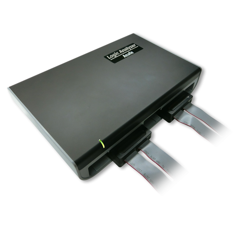
Acute Instruments Supporting I2C
Recommended Solutions

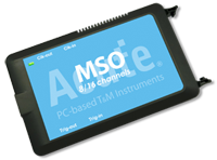

All Supporting Products


PX2000 Series

Ready to analyze this protocol?
See how Acute instruments capture and decode this protocol in real time. Request a demo or contact our team.
How to Analyze I2C with Acute Instruments
Connect your Acute logic analyzer to the SDA and SCL lines of the I2C bus using the included probes.
Attach a ground lead to the target board's ground reference.
In the Acute software, select the I2C protocol decoder and assign SDA and SCL to the correct input channels.
Configure the expected bus speed (100 kHz, 400 kHz, 1 MHz, or 3.4 MHz) and address format (7-bit or 10-bit).
Trigger a capture and view decoded transactions showing START/STOP conditions, slave addresses, R/W bits, data bytes, and ACK/NACK responses.
Related Articles
How to Choose the Right Logic Analyzer for Your Project
A practical decision guide for selecting the right Acute logic analyzer or MSO by channel count, sample rate, protocol decode, and portability requirements.
PX2816B Protocol Exerciser: Stimulus and Response Testing for Embedded Interfaces
How the PX2816B Protocol Exerciser generates protocol stimulus, validates device responses, and automates compliance testing for I2C, SPI, UART, and MIPI I3C.
Getting Started with Acute Test Instruments
First-time setup guide for Acute instruments — software installation, USB connection, first capture, and basic protocol decode configuration for I2C, SPI, and UART.
I2C Downloads & Resources
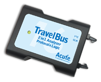
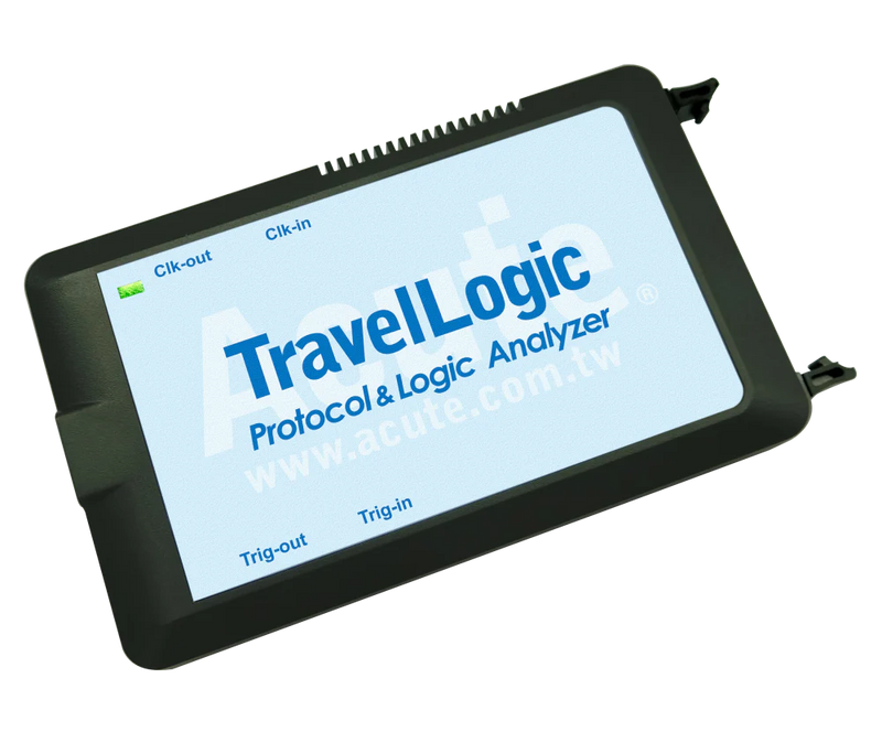
Software
Application software for the TravelBus protocol and logic analyzer series. Windows 10/11.
Linux application for the TravelBus series. Separate native Linux app (not a Windows port) — currently in beta. Download the latest release from GitHub.