BusFinder Add-Ons
SKU: BF-LA-PROBE
Specifications
-
LA-Pod Solution:
Accessories Description 
1. LA08-tip: 8 Data Channel
2. LA09-tip: 8 Data Channel + 1 CLK Channel
3. Operation Voltage: -1V~8V
4. Timing Analysis: 2.4 GHz
Software:


-
eDP1.4a:
Functions:
– Support eDP 1.4a,Up to 5.4Gbps,4 Lanes
– Use 32Gb RAM as the buffer to stream all eDP data into the SSD HD in order to record all data flow from Low Power Mode to High Speed Mode
– Data Filter: filters unwanted Dummy, Video data, Filling S/E to save memory
– Search: searches specific data
– Display eDP image data including RGB, YCbCr, format or compressed DSC packets.
– eDP command statistics include numbers of packets, individual command, different data length, and errors
– eDP command triggerDescription:
BusFinder device, when paired with the eDP 1.4a solution, is capable of measuring eDP V1.4a protocol analysis.Display eDP1.4a protocol packet data in table format, including DP Aux Ch command analysis

eDP Lane Skew display and statistics

Display eDP image data including RGB, YCbCr, format or compressed DSC packets. eDP command trigger, can trigger external oscilloscopes synchronously 

-
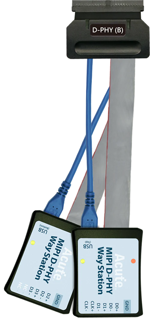
MIPI D-PHY:
D-PHY command statistics include numbers of packets
Features:
– Supports D-PHY V1.2, Up to 2.0Gbps per lane, 1 + 4 Lanes
– Display the CSI-2 1.3 or DSI 1.3 packet data in table, Includes DCS 1.3 command analysis for DSI
– Fully capture the data from Low Power Mode Initialize to High Speed Mode process
– Supports Data Filter for ignore unnecessary image data to reduce memory
– Supports Data Search function
– Supports ECC/CRC Packet Error counting and display
– Display DSI(CSI) image data including RGB, YCbCr, RAW format or compressed DSC packets, and count the Porch from raw data.
– D-PHY command statistics include numbers of packets, individual command, different data length, and errors.
– TE (Tearing Effect) Channel Detection
Description:
BusFinder with MIPI D-PHY Solution ( Way station and other components). Supports MIPI D-PHY 1.2CSI-2 1.3 or DSI 1.3 protocol packets displayed as below with the DSI DCS 1.3 commands

Display DSI(CSI) image data Porch from raw data 


-
SD 4.1 (UHS II) Solution:
Features:
– Supports SD4.0 (UHS-II) Trigger、Protocol Analyzer
– Supports SD4.0 (UHS-II),Up to 1.56Gbps per laneDescription:
– The order to record all data flow from Low Power Mode to High-Speed Mode.
– “Data Filter” filters unwanted data to save memory.
– “Search” searches specific data.
– “CRC Packet” displays and counts CRC
– Can display SD4.0 protocol packet data in tabular form, including command parsing
– SD4.0 command statistics include numbers of packets, individual commands, different data lengths, and errors
– SD4.0 command trigger
– VDD DetectionCan display SD4.0 protocol packet data in tabular form, including command parsing
 SD 4.0 command statistics
-
NAND Flash Solution:
Features:
– Support Data(I/O) pin: x8, x16
– Support Various Vendors: Hynix, Intel, Micron, Samsung, ST, Toshiba, Winbond, Macronix, Cypress(Spansion), ONFI, Dosilicon, ESMT, Zetta, GigaDevice, etc. (Also support Custom data)
– Support ONFI 4.1(NV-DDR3),Mode 8 / Toggle DDR 2.0 ~267MHz
– Timing Check (Logic Analyzer Mode Only. It can be enabled in bus decode settings.)Description:
Display NAND Flash protocol packet in tabular form, including command parsing
– Use 32Gb RAM as the buffer to stream all NAND Flash data into the SSD HDD to record all data flow from the Low-Speed Mode to the High-Speed Mode.
– Filtering unwanted data.
– Searching for specific data.
– Counting the times of erasing blocks.
– Statistics of NAND command includes numbers of packets and individual command.
Statistics of NAND command includes numbers of packets Individual command 

NAND trigger

Customize the NAND Command Set

-
eMMC 5.1:
Features:
– Supports eMMC version up to 5.1 HS400 / HS200 / CMD Queue
– 3-Pin Mode:If you only need to analyze the waveform data of CMD and BUSY, 3-Pin Mode will be a good choice. You do not need to connect all the pins in the measurement. You only need to connect the CLK, CMD, and D0 pins to measure the CMD data.
– No Clk Mode:If you need to record the CMD waveform data for a long time, you can ONLY connect CMD pin. Then you can do the CMD analysis with transitional storage.Description:
– The order to record all data flow from Low Power Mode to High-Speed Mode.
– “Data Filter” filters unwanted data to save memory.
– “Search” searches specific data.
– “CRC Packet” displays and counts CRC
– Can display eMMC/MMC 5.1 protocol packet data in tabular form, including command parsing
– eMMC/MMC 5.1command statistics include numbers of packets, individual commands, different data lengths, and errors
– eMMC/MMC 5.1 command trigger
1. Settings 2. Data Phase Tuning 

3-Pin ModeNo Clk Mode
Can display eMMC protocol packet data in tabular form, including command parsing

-
SD3.0/SDIO3.0:
Functions:
– Supports SD 3.0 SDR104 / SD6.0 Legacy mode SDR104, DDR200/ SDIO 3.0
– 3-Pin Mode:If you only need to analyze the waveform data of CMD and BUSY, 3-Pin Mode will be a good choice. You do not need to connect all the pins in the measurement. You only need to connect the CLK, CMD, and D0 pins to measure the CMD data.
– No Clk Mode:If you need to record the CMD waveform data for a long time, you can ONLY connect CMD pin. Then you can do the CMD analysis with transitional storage.Description:
– The order to record all data flow from Low Power Mode to High-Speed Mode.
– “Data Filter” filters unwanted data to save memory.
– “Search” searches specific data.
– “CRC Packet” displays and counts CRC
– Can display SD6.0 Legacy mode / SD 3.0 protocol packet data in tabular form, including command parsing
– SD6.0 Legacy mode / SD 3.0 command statistics include numbers of packets, individual command, different data length, and errors
– SD6.0 Legacy mode / SD 3.0 command trigger
– SD6.0 Legacy mode Command Queue
– Support SDR12、SDR25、SDR50、SDR104、DDR50、DDR200
*BusFinder provides 3 different kinds of adaptors which you can choose3-Pin Mode

No Clk Mode

SD 3.0 command statistics (Protocol Analyzer) Diagram

-
SGMII Solution:
Features:
– Simultaneously display PCS or GMII protocol packet data in tabular form, including command parsing.
– “Data Filter” & “Idle Filter” filter unwanted data and idle to save memory.
– “Search” searches specific data.
– SGMII PCS & GMII statistics include numbers of packets, individual command, different data length, and errors.
– Support 10Mbps/100Mbps/1000MbpsDescription:
SGMII command trigger
a. Trigger parameters include commands and data in order to cover all kinds of packets.
b. GMII & PCS Packet
c. Trigger CRC Error, Frame Error, Propagation Error, Start of Packet, End of Packet, Carrier Extend, Configuration.
d. The Trigger-Out port is to trigger a DSO to capture waveforms
SGMII command trigger- PCS Trigger SGMII command trigger- GMII Data Trigger 

SGMII(PHY) & GMII(MAC) packet analysis data are displayed simultaneously in the report table. The report also contains statistics on packets.

-
UFS2.1(BF7264B+ Only) Solution:
Features:
– Supports MIPI M-PHY 3.0, Up to 5.8Gbps ( Gear 3, Rate A / B ), 2 Lanes
– Can simultaneously display Unipro or UFS protocol packet data in tabular form, including command parsing
– Use 32Gb RAM as the buffer to stream all M-PHY data into the SSD HD in order to record all data flow from PWM Mode to High Speed Mode.
– “Data Filter” filters unwanted data to save memory.
– “Search” searches specific data.
– “CRC Packet” displays and counts CRC
– Unipro / UFS command statistics include numbers of packets, individual command, different data length, and errors
Simultaneously display Unipro Simultaneously display Unipro or UFS protocol packet data in tabular form Including command parsing 


Unipro / UFS command statistics include numbers of packets, individual command, different data length, and errors Unipro, UFS Command trigger 

Supported Protocols
Related Articles
MIPI I3C Protocol Analysis: Capturing and Debugging Next-Gen Sensor Buses
Complete guide to MIPI I3C protocol analysis — from basic bus capture to advanced HDR mode decode, in-band interrupts, and I2C backward compatibility validation.
CAN FD Protocol Analysis for Automotive Electronics
How to capture, decode, and analyze CAN FD bus traffic using Acute protocol analyzers and logic analyzers for automotive electronics development.
eSPI Bus Analysis for Intel Platform Validation
How to capture and analyze eSPI (Enhanced Serial Peripheral Interface) bus traffic for Intel platform bring-up, EC firmware debugging, and system validation.
Downloads
Software
Application software for BusFinder protocol analyzers, LA3000, and LA4000 logic analyzers. Windows 10/11.
Linux application for the BusFinder and LA4000 series. Separate native Linux app — currently in beta. Download the latest release from GitHub.
SDK & API
Not sure which instrument is right for your application?
Our engineering team can help you match the right instrument to your specific protocol, channel count, and performance requirements.